

Elevator shaft dimensions design
Basic requirements in elevator shaft size design
The design and dimensions of the elevator shaft are crucial factors determining the operational efficiency and safety of the elevator system. The shaft dimensions must ensure sufficient space for the cabin, counterweight, guide system, and other technical equipment. Simultaneously, it must comply with international standards and local building regulations to ensure legality and safety during use.
Typically, elevator shaft dimensions are determined based on the type of elevator (passenger elevator, freight elevator, hospital elevator, etc.), load capacity, and the expected number of users. Dimension calculations should be based on the manufacturer's specifications for the cabin and equipment, and must also allow for space for maintenance and repairs.
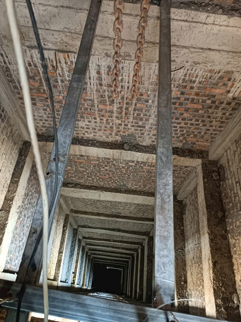
Standards and regulations regarding elevator shaft dimensions
Globally, standards such as EN 81 (Europe), ASME A17.1 (USA), and TCVN (Vietnam) specify detailed dimensions for elevator shafts to ensure safety and operational efficiency. For example, according to EN 81, the width and depth of the elevator shaft must be sufficient to accommodate the cabin and counterweight, while maintaining a safe distance between components to prevent collisions.
In Vietnam, the TCVN 6390:2018 standard for elevators clearly specifies the dimensions of elevator shafts, including:
- Elevator shaft width: Must be at least 200 mm wider than the elevator cabin width to ensure sufficient space for installation and operation.
- Elevator shaft depth: Must be at least 200 mm greater than the cabin depth, and must also account for space for the counterweight and guide system.
- Elevator shaft height: It must be large enough to accommodate the cabin when traveling to the highest floor and have safe clearance above the shaft.
Adherence to these standards not only helps ensure safety but also facilitates maintenance and repair processes.
Factors affecting elevator shaft size design
The design dimensions of an elevator shaft are not only based on the cabin size but are also influenced by many other factors:
Elevator type and load capacity
Passenger elevators typically have smaller shafts compared to freight elevators or hospital elevators due to differing load capacity and cabin size requirements. For example, freight elevators require a wider and deeper shaft to accommodate larger cabins and heavier counterweights.
Building location and structure
The building's layout and structure also influence the size of the elevator shaft. In older buildings or those with limited space, elevator shaft design needs to be optimized to maximize area utilization while ensuring safety and operational efficiency.
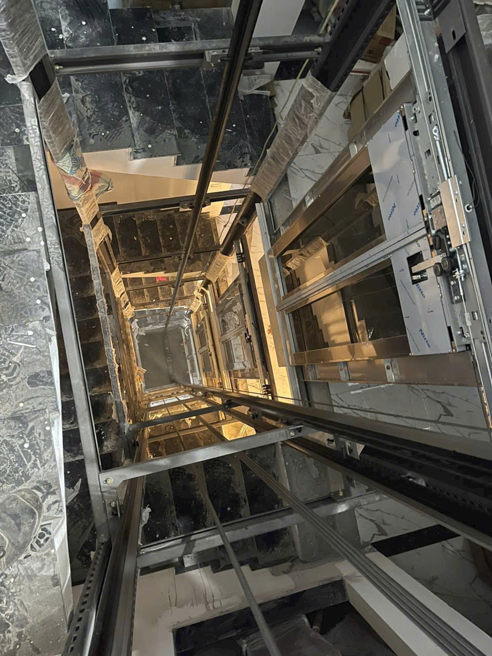
The accompanying mechanical and electronic systems.
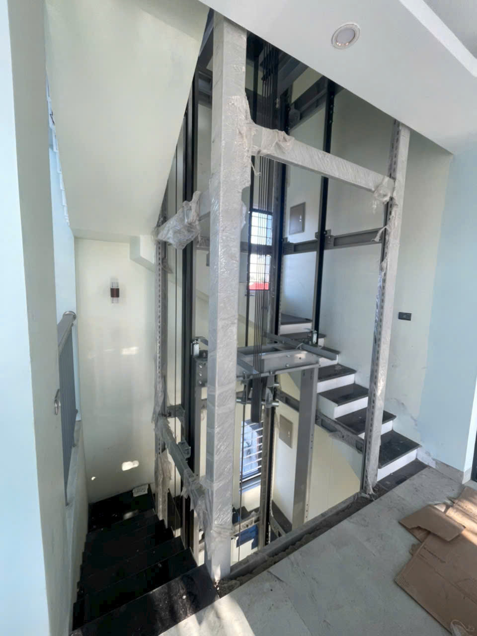
The elevator shaft needs sufficient space to install the guide system, counterweight, control unit, traction cables, and other safety devices. Proper placement of these components in the shaft helps minimize accidents and increase the lifespan of the elevator.
Methods for calculating and designing elevator shaft dimensions
The elevator shaft design process typically begins with selecting a cabin that suits the intended use. Then, based on the cabin dimensions, engineers calculate the necessary safety distances to determine the elevator shaft size.
The basic steps in designing elevator shaft dimensions include:
- Determine cabin dimensions: The width, depth, and height of the cabin should be based on the load capacity and the number of users.
- Calculating space for counterweights: Counterweights are typically the same size as or larger than the cabin to balance the load.
- Locating the guidance system and technical equipment: Determine the installation locations for guide rails, controllers, traction cables, and safety devices.
- Precautionary safety distances: Add minimum distances between the cabin, counterweight, and pit walls to ensure safety and convenience for maintenance.
- Compliance check: Ensure the elevator shaft dimensions comply with international standards and local regulations.
Using specialized design software helps optimize elevator shaft dimensions, minimize errors, and save on construction costs.
Important considerations when designing elevator shaft dimensions.
During the design process, the following points should be considered to ensure efficiency and safety:
- Space for maintenance: The elevator shaft design must provide sufficient space for technicians to easily access and maintain the equipment.
- Ensure adequate ventilation and lighting: Elevator shafts need proper ventilation and lighting to ensure safety when working inside.
- Choose appropriate building materials: The materials used for the elevator shaft must withstand heavy loads and harsh environmental conditions.
- Accurate load calculation: The elevator shaft dimensions must be suitable for the maximum load capacity of the elevator to avoid the risk of damage or accidents.
- Collaboration with relevant departments: The design needs to be closely coordinated with architects, structural engineers, and elevator suppliers to ensure feasibility and efficiency.
To ensure your elevator shaft design meets standards and is optimized, contact elevator experts for detailed advice and support.
Elevator shaft dimensions design
Technical basis for designing elevator shaft dimensions
Designing the elevator shaft dimensions is a fundamental step that determines the installation, stable operation, and safety of the entire system. Shaft dimensions depend not only on the load capacity, speed, and type of elevator (residential elevator, passenger elevator, hospital elevator, cargo elevator) but also on architectural constraints, safety standards, and actual construction conditions. A properly designed shaft will optimize construction costs, reduce vibration and noise, minimize installation errors, and extend equipment lifespan.
In principle, elevator shaft dimensions must be determined simultaneously with the architectural and structural design phases of the building. Engineers need to coordinate closely with the elevator supplier to agree on the shaft's internal dimensions , floor door clearances , pit depth , overhead height (OH) , and technical clearances for guide rails, cables, counterweights, and electrical cabinets. Any discrepancies between the architectural drawings and the elevator drawings can lead to demolition, reinforcement, or changes to the elevator model, resulting in significant additional costs.
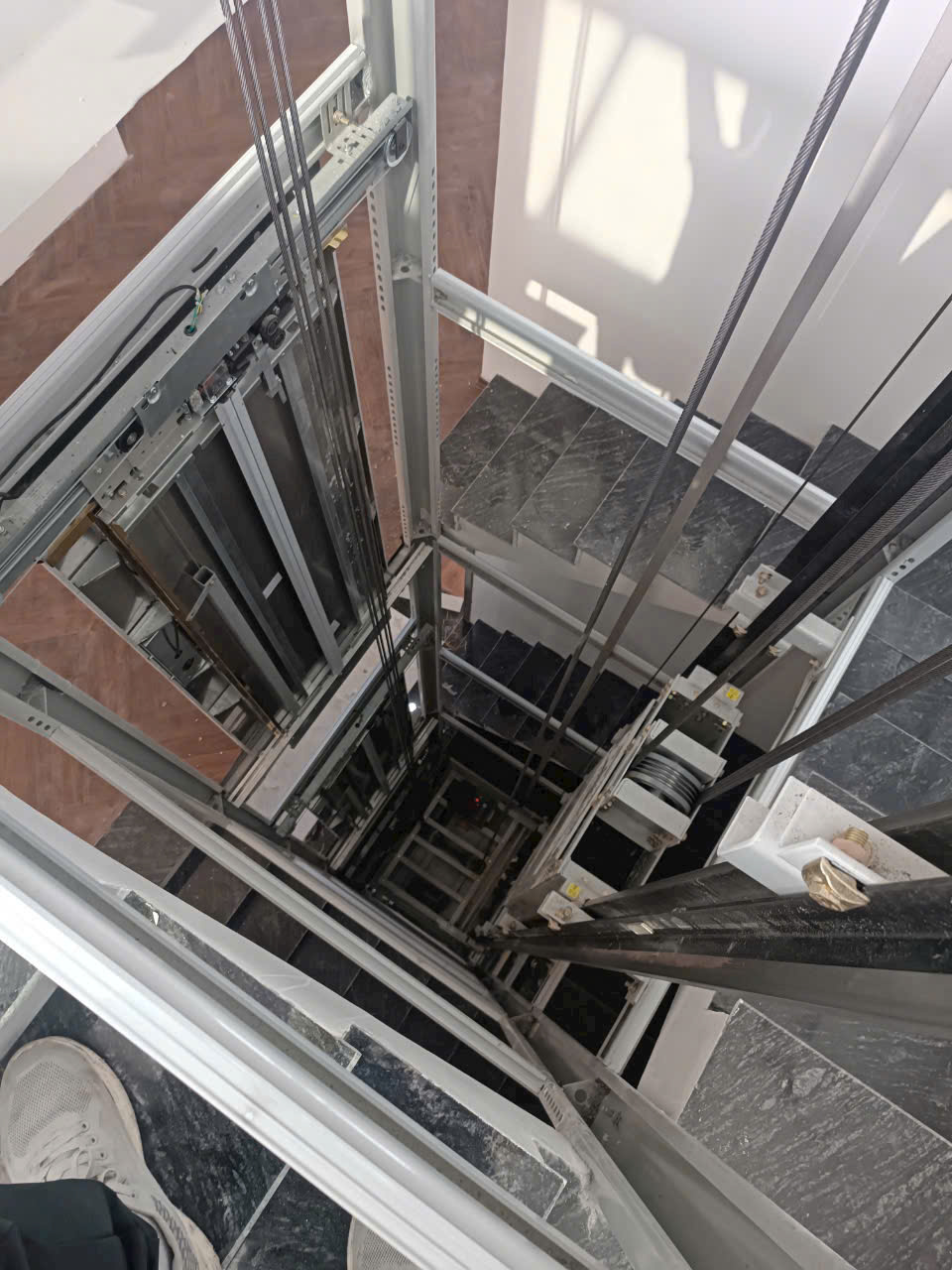
Important elevator shaft dimensions
When implementing the design, it is necessary to clearly define the core dimensional parameters, where each parameter is associated with specific technical and safety criteria. A thorough understanding of the meaning of each dimension helps architects and structural engineers proactively arrange space, avoiding conflicts with beams, columns, utility boxes, and MEP shafts.
Elevator shaft internal dimensions (Width x Depth)
The internal dimensions of the elevator shaft refer to the usable space inside the shaft, measured from one finished wall surface to the opposite finished wall surface. This parameter directly determines the cabin size , rated load capacity , and the type of door that can be used. For home elevators with a load capacity of 300–450 kg, the internal dimensions typically range from 1400–1600 mm (width) and 1300–1500 mm (depth), while passenger elevators with a load capacity of 1000–1600 kg require a significantly larger shaft. When designing, it is necessary to add the thickness of the finished walls, waterproofing layer, and decorative cladding to avoid discrepancies in actual dimensions.
For elevators with side counterweights , the shaft width must be sufficient for the cabin, safety clearance, and counterweight rails. For elevators with rear counterweights , the shaft depth will increase. The choice of counterweight placement should be considered early to avoid intersections with beams, staircases, or other utility shafts. In all cases, the safety clearance between the cabin, counterweight, and shaft wall must comply with current TCVN/EN standards.
Pit depth and overhead height
The depth of the elevator pit (measured from the lowest floor level to the bottom of the pit) is a crucial parameter for arranging cabin shock absorbers , counterweight shock absorbers , space for sensors and cables, and safety clearance for maintenance personnel. The higher the elevator speed and the greater the load, the deeper the pit required. For low-speed residential elevators, a shallow pit solution combined with special shock absorbers can be used, but it must still meet minimum safety criteria regarding protective space.
Overhead (OH) height is the distance from the floor level of the top floor to the highest point in the elevator shaft (usually the bottom of the roof beam or the machine room floor). OH must be sufficient to accommodate pulley supports , shock absorbers , limit switches , and to create a safe zone for technicians when the elevator reaches the highest floor. For renovation projects with limited floor height, a machine-roomless elevator or a solution to reduce OH as recommended by the manufacturer may be considered, but under no circumstances should the safety distance be reduced without authorization.
Floor door dimensions and door setback
The dimensions of landing doors (width x height) directly affect accessibility , traffic flow , and user convenience . Hospital elevators, patient elevators, and freight elevators require significantly wider doors than typical passenger elevators. When designing the elevator shaft, sufficient setback space must be provided for the automatic door mechanism, suspension rails, drive system, and safety sensors. The walls on either side of the door must be thick and strong enough to support the door frame, preventing cracking during long-term operation.
In cases where the door opens towards a narrow lobby, the space in front of the door must be calculated to ensure convenient access for users without obstructing emergency exits. Accessibility design standards for people with disabilities also require minimum door widths and wheelchair turning space; therefore, the size of the elevator shaft and the location of the door must be considered within the overall floor plan.
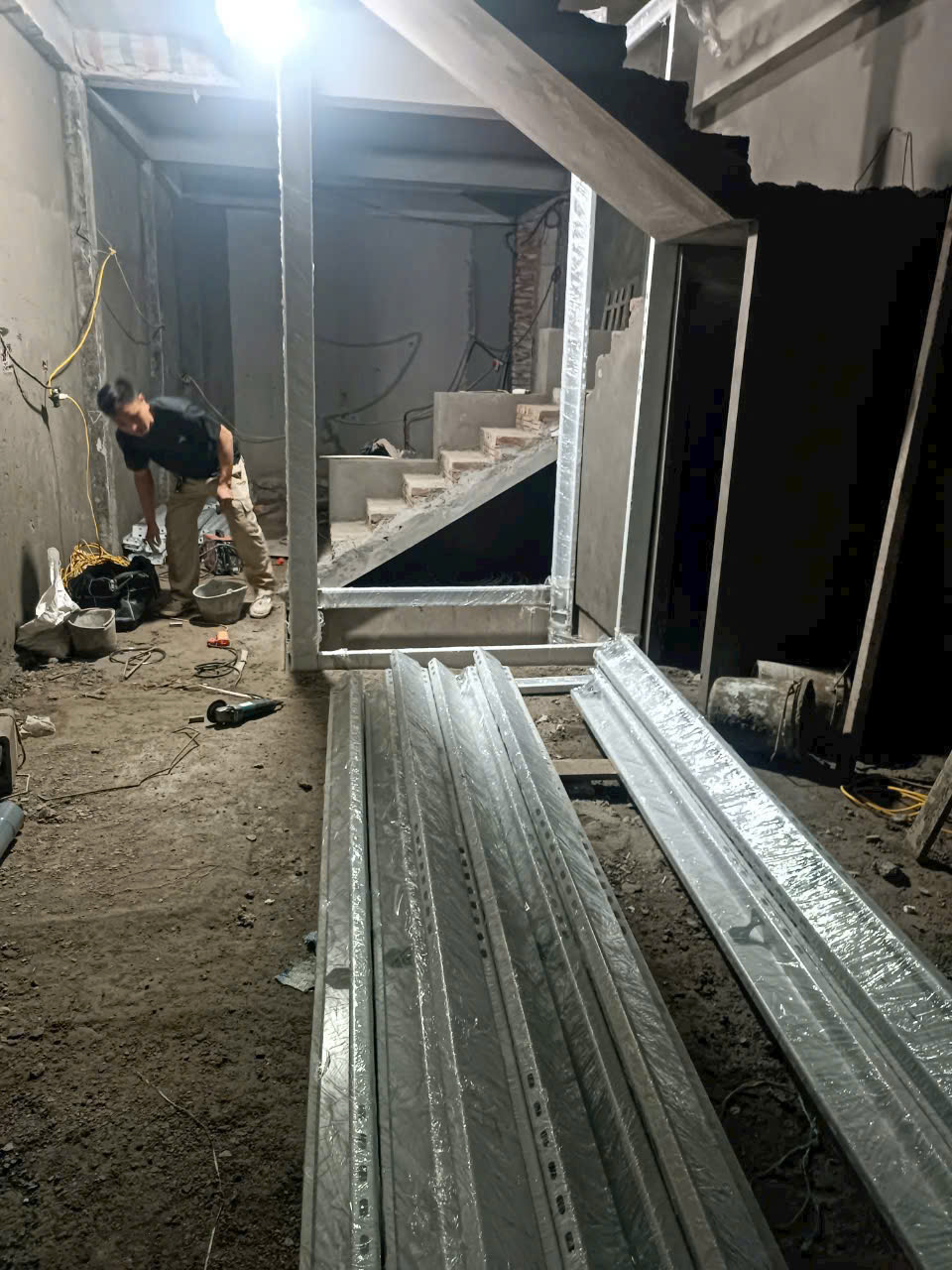
Technical criteria and standards applicable to elevator shafts.
The design dimensions of an elevator shaft must comply with elevator safety standards , building codes , and manufacturer requirements simultaneously . Relying solely on experience or sample drawings without referencing standards can lead to dangerous discrepancies, especially in areas such as safety clearances, rescue access, and the load-bearing capacity of the enclosure structure.
The technical criteria that need to be strictly controlled include: minimum clear dimensions , safe clearance between cabin – counterweight – wall , load-bearing capacity of the pit walls , flatness and verticality of the surface , waterproofing and drainage capabilities for the pit , and space for installing electrical cabinets, cables, and cable trays . Each criterion has a specific limit in the standard and cannot be arbitrarily reduced to save space.
Requirements for elevator shaft structure and materials
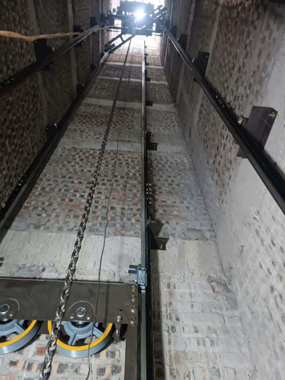
Elevator shafts are typically constructed using reinforced concrete or brick walls combined with a concrete frame , depending on the elevator load and overall structural design. For high-load, high-speed elevators, a monolithic reinforced concrete shaft is preferred to ensure rigidity, minimize vibration, and extend the lifespan of the guide rails. The shaft wall surface must be plastered smooth, with tolerances within the manufacturer's requirements, to ensure accurate rail and equipment alignment.
The pit bottom must be designed to be waterproof , with a drainage manhole and pump if the structure is at risk of flooding or has a high groundwater level. The reinforcement and thickness of the bottom slab must be sufficient to withstand the concentrated load from the cabin shock absorbers and counterweights. In many cases, anchor points or gusset plates need to be installed in the pit walls to attach rails, door frames, and cable trays; if omitted during the design phase, adding them later will be very difficult and costly.
Safety, rescue, and maintenance space
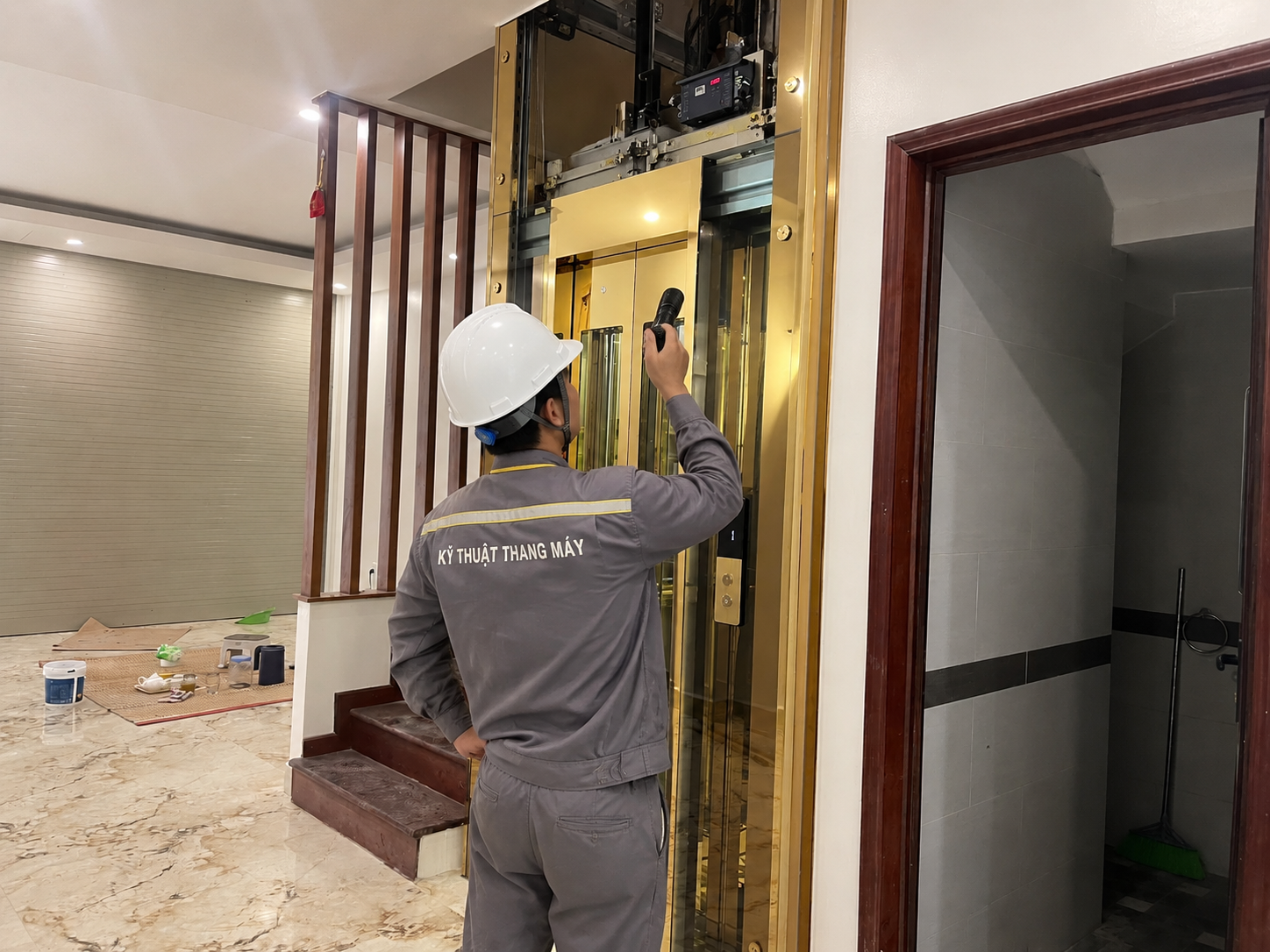
The space within the elevator shaft must ensure safe access for technicians during inspection, maintenance, and rescue operations. This is directly related to the dimensions of the pit, overhead space, and surrounding technical clearances. A fixed steel ladder , a safe standing point , and technical lighting should be provided in the pit to facilitate operation. Limit switches, door safety switches, and emergency stop devices must be installed in easily accessible areas, not obscured by the shaft structure.
In the design, technical space should be allocated for future replacement of cables, pulleys, traction machines, automatic rescue systems, or speed upgrades. Minimizing pit size to the absolute limit may save space in the short term but will increase maintenance costs, make upgrades more difficult, and pose risks when emergency intervention is needed.
Optimal elevator shaft dimensions and implementation recommendations.
To optimize elevator shaft dimensions, a synchronized approach to architectural, structural, and equipment solutions is necessary from the initial design phase. Instead of choosing shaft dimensions based on intuition, it's advisable to work directly with the elevator supplier to obtain a standard layout drawing , and then adjust the building's floor plan around the elevator axis. This approach helps avoid the problem of "cramming the elevator into an empty space," which is a major cause of distorted or misaligned shafts and installation difficulties.
Commonly applied optimal solutions include: choosing machine-roomless elevators to reduce building height; using small, single-sided elevators for narrow townhouses; placing counterweights on the sides to reduce pit depth in confined spaces; and applying shallow pit solutions for renovation projects where deep excavation is not feasible. Each option requires detailed calculations regarding dimensions, load capacity, safety standards, and practical construction feasibility.
To ensure that the elevator shaft dimensions are designed to be standard and efficient, the following specific action steps should be taken:
- Communicate with the elevator consulting firm early on , right from the preliminary design stage.
- Detailed technical drawings are required : pit plan, cross-section, load diagram, and structural requirements.
- Coordinate architecture, structure, and MEP to avoid spatial conflicts around the elevator shaft.
- Strictly control the actual construction dimensions compared to the drawings, especially the pit and overhead dimensions.
- Assess the rescue and maintenance plan in advance to ensure sufficient space is left for technical operations.
- Refer to current standards, regulations , and the manufacturer's technical documentation before finalizing the dimensions.
To minimize risks, save costs, and ensure long-term safety, proactively contact elevator specialists right from the start of the building design process. Request them to propose the optimal elevator shaft dimensions , along with clear technical specifications and a commitment to support throughout the construction, installation, and operation phases.